The WS2812 family is a intelligent control LED light source that the control circuit and RGB chip are integrated in a package of 5050 components. It internal include intelligent digital port data latch and signal reshaping amplification drive circuit. effectively ensuring the pixel point light color height consistent.
The data transfer protocol use single NZR communication mode. After the pixel power-on reset, the DIN port receive data from controller, the first pixel collect initial 24 bit data then sent to the internal data latch, the other data which reshaping by the internal signal reshaping amplification circuit sent to the next cascade pixel through the DO port.
After transmission for each pixel,the signal to reduce 24bit. pixel adopt auto reshaping transmit technology, making the pixel cascade number is not limited the signal transmission, only depend on the speed of signal transmission. LED with low driving voltage, environmental protection and energy saving, high brightness, scattering angle is large, good consistency, low power, long life and other advantages.
The control chip integrated in LED above becoming more simple circuit, small volume, convenient installation
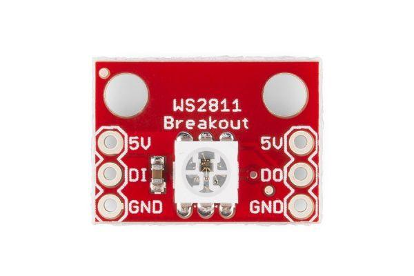
I bought a little breakout, here is a picture of this part

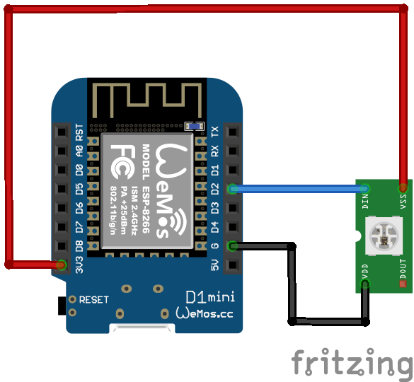
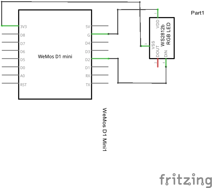
Schematics and layout
Here are schematics and layout for connecting one of these breakouts


Code
You will need to import the Adafruit Neopixel library from https://github.com/adafruit/Adafruit_NeoPixel
[codesyntax lang=”cpp”]
#include <Adafruit_NeoPixel.h>

#define PIN D2
// How many NeoPixels are attached to the Arduino?
#define NUMPIXELS 1

Adafruit_NeoPixel pixels = Adafruit_NeoPixel(1, PIN, NEO_GRB + NEO_KHZ800);

void setup()
{
 pixels.begin();
}

void loop()
{
 int delayval = 500; // delay for half a second
 // For a set of NeoPixels the first NeoPixel is 0, second is 1, all the way up to the count of pixels minus one.

 for(int i=0;i<NUMPIXELS;i++)
 {
 // pixels.Color takes RGB values, from 0,0,0 up to 255,255,255
 pixels.setPixelColor(i, pixels.Color(0,255,0));
 pixels.show();
 delay(delayval);
 pixels.setPixelColor(i, pixels.Color(255,0,0));
 pixels.show();
 delay(delayval);
 pixels.setPixelColor(i, pixels.Color(0,0,255));
 pixels.show();
 delay(delayval);
 }
}
[/codesyntax]
Links
10PCS/LOT WS2812 RGB LED Breakout Module For Arduino


Hello!
I wonder why you connect the 3.3V tot eh LED, while the red pcb says 5V?
hope you can help me.
thank you!
‘the led’*
The board (LED) works at 3.3v as well
Ok thanks!
But won’t the led be dimmed? Would it work properly if you powered the led with external 5v supply and only connect data wire from D1 board?
Possibly, it would depend on the specs of the WS2812B and the Wemos. There is a possible solution if you have issues at http://hackaday.com/2017/01/20/cheating-at-5v-ws2812-control-to-use-a-3-3v-data-line/ or use a level shifter. I’ve never had an issue personally.
Hi, I am using WeMos D1R2 Board, and tried your code but i RGB light is not working. Can you please help
Amir