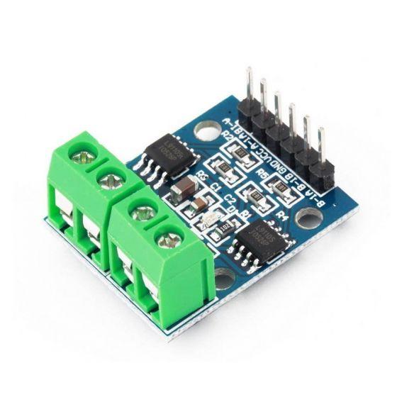
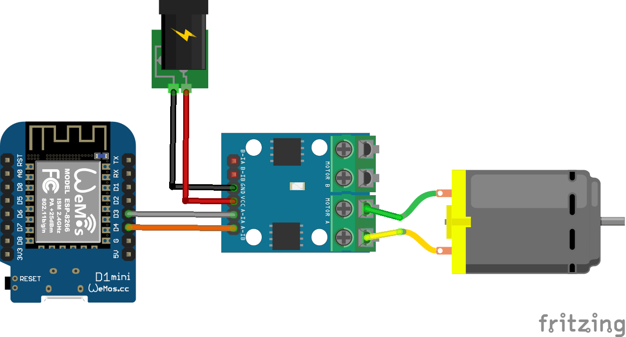
In this example we connect an ESp8266 to a dual L9110 fan module. This is a commonly found, basic low cost module which consists of an L9110 chip and a small motor attached. You need 4 connections between the arduino and the module. VCC, GND , INA and INB. You should use an external power source for Vcc and Gnd
L9110 The ASIC device control and drive motor design two-channel push-pull power amplifier discrete circuits integrated into a monolithic IC, peripheral devices and reduce the cost, improve the reliability of the whole. This chip has two TTL / CMOS compatible with the level of the input, with good resistance; two output terminals can directly forward and reverse movement of the drive motor, it has a large current driving capability, each channel through 750 ~ 800mA of continuous current, peak current capability up to 1.5 ~ 2.0A; while it has a low output saturation voltage; built-in clamp diode reverse the impact of the current release inductive load it in the drive relays, DC motors, stepper motor or switch power tube use on safe and reliable. L9110 is widely used in toy car motor drives, stepper motor drive and switching power tube circuit.
- Motor Voltage: 2.5 ~12V
- Motor channels: 2
- Max Continuous Current per Channel: 800mA
- Size: 31mm x 22mm x 12mm
this is a picture of a typical module

Lets look at how to connect the ESP8266 to the module
Layout

Code
No libraries needed in this example, fairly basic example this one, upload the sketch and the fan will just run in one direction at one speed. You could use analogWrite and set a value between 0 and 255, if you have one of the dual modules you can have 2 motors fitted and technically move in any direction
[codesyntax lang=”cpp”]
int INA = D3;
int INB = D4;

void setup()
{
pinMode(INA,OUTPUT);
pinMode(INB,OUTPUT);
}

void loop()
{
digitalWrite(INA,LOW);
digitalWrite(INB,HIGH);
delay(1000);
}
[/codesyntax]
Link

